Anderson Power Pole
Tester
By Paul Curry – K6PEC
Introduction
Build this little tester or several for your Emcomm go kit, tool box or whatever.
I thought that I would share a quick little tester that I built recently. I found a need for such a tester as I was testing a portable radio station using a 90Ah battery with a West Mountain Rig Runner. I wanted a quick indication of power availability at the Power Pole connectors on the Rig Runner. I also thought it would be nice to know if the provided power was of the correct polarity as to what I was expecting. That, in a nutshell, explains the motivation behind this little tester idea.
This little project will provide an Anderson Power Pole connector tester that will light up if power is present: green if the power is of the correct polarity and red if polarity is incorrect. The basis of this tester is a simple bi-color (bi-polar) (red/green) LED with current limiting resistor mounted in Power Pole connectors.
I also want to add this tester is not intended to replace a voltmeter or DMM, but is intended to serve as a quick “go/no-go” indication.
It is difficult for me to believe that a similar project or whatever doesn’t already exist, but I did not know of it. Assuming that something else similar does exist, I offer my version for your consideration.
Parts List
The parts and procedures for building this tester are detailed below:
Ø 1 Bi-polar / color LED (e.g. Radio Shack 276-012 Or Kingbright – WP57EGW Mouser Electronics Part Number 604-WP57EGW)
Ø 1 Resistor ¼W 1K Ohm (not critical, could be slightly less or more – I happened to have many of this value on hand, making this my selection. Resistors available from Radio Shack, Mouser or other electronics stores)
Ø 2 15A Power Pole connector
Ø 1 Red and 1 Black Power Pole connector shells
Ø 1 Power Pole roll pin
Ø 1 Power Pole connector cover boot
Ø Some sort of Adhesive / Sealer (I used Goop Adhesive / Sealer. Sticks to most surfaces and serves as a good sealer also)
One source for the Power Pole connectors, roll pin and cover boot is powerwerks .com. I am sure there are other sources though, HRO is probably one.
See the picture below showing the parts.
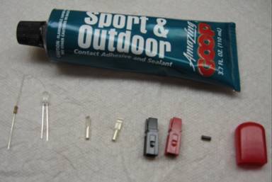
Parts Used In Power Tester
Assembly
Details
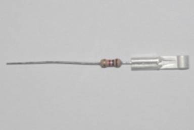
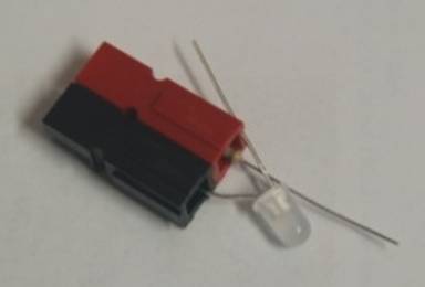
1. Cut approximately ⅝” off one end of the resistor and crimp this end into a 15A Power Pole connector.
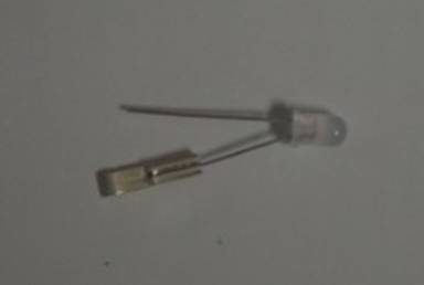
2. Cut approximately ¼” off long lead of LED. Insert this lead into a 15A Power Pole connector. Keep in mind that this newly cut lead will be the shorter one.
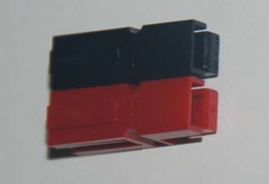
3. Assemble the red/black Power Pole connector shells as shown in the picture (ARES standard, blade down, red on right, viewed from the wire side of the connector)
4. Snap the resistor leaded Power Pole connector into the red Power Pole shell. You may want to use a small flat-blade screwdriver to assist in snapping the connector into place. Similarly snap the LED leaded Power Pole connector into the black Power Pole shell.
6. Twist, solder and trim the resistor and LED leads together.
7. Install the Power Pole Connector roll pin.
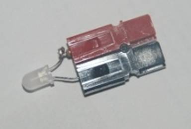
8. Apply an adhesive / sealant to hold everything in place. I used Goop Sport and Outdoor. This stuff sticks to most surfaces and provides a good non-conductive sealing action (see picture). This may take more than one application since it may require a relatively thick coat to complete the entire package. Let this dry per instructions of the product used. I let it dry for 24 hours.
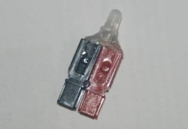
9. Trim approximately ¼” off the length of a red plastic boot cover. It is actually longer to cover the entire connector as a protective cover, but we are using it here to cover our connections and serve as a light duty mechanical protection for the connection and LED.
10. Then punch and trim a hole in the end of the red plastic cover boot for the LED to be inserted through.
11. Assemble the red plastic cover boot over the LED to complete the assembly.
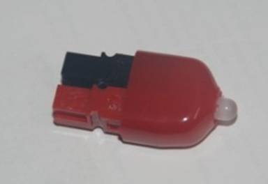
12. Now you can test it on a known good source of power and reverse the polarity of the power to check that red is illuminated and green for a correct polarity connection.
Conclusion
Hopefully, this little project may prove useful for you. If there are any questions, please feel free to contact me.
As usual, all the standard disclaimers apply e.g. may not be suitable for small children or pets or for all applications, do not attempt to build if under the influence of substances, … etc.
![]()